Description
Key Features
- Measures water flow accurately using a Hall-effect sensor.
- Simple 3-wire connection (VCC, GND, Signal).
- Compatible with most microcontrollers like Arduino, Raspberry Pi, and ESP boards.
- Durable plastic body with high corrosion resistance.
Specifications
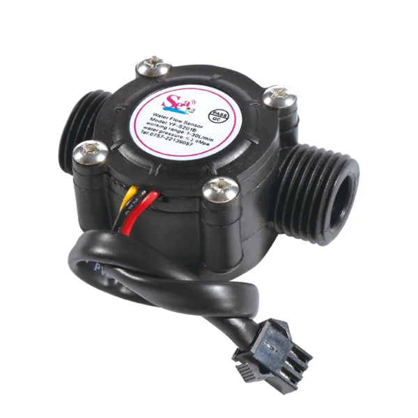
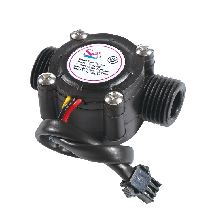
- Model: YF-S201B
- Operating Voltage: 5V–18V DC
- Output Signal: Pulse signal (Hall effect sensor)
- Flow Rate Range: 1–30 liters per minute (L/min)
- Pulse Frequency: 4.5 pulses per liter (approx., varies by water pressure and pipe conditions)
- Accuracy: ±10%
- Maximum Pressure: ≤ 1.75 MPa
- Pipe Diameter: G1/2 (1/2 inch)
- Working Temperature: -20°C to 80°C
- Material: Food-grade plastic
Working Principle
- The sensor has a rotor with blades inside the water passage.
- As water flows, the rotor spins, and a Hall-effect sensor detects the magnetic pulses generated by the spinning rotor.
- The output is a pulse signal, where the frequency corresponds to the flow rate.
Pinout
- Red Wire: Power (VCC)
- Black Wire: Ground (GND)
- Yellow Wire: Pulse Signal (Connect to a GPIO pin)
Formula to Calculate Flow Rate
The pulse frequency output by the sensor can be used to calculate the flow rate using the formula:
Q=PulseFrequencyK×TQ = frac{PulseFrequency}{K times T}Q=K×TPulseFrequency
Where:
- Q: Flow rate in liters per minute (L/min)
- PulseFrequency: Measured pulses per second
- K: Calibration factor (usually 4.5 pulses per liter, check the datasheet)
- T: Time interval (seconds) over which pulses are measured
Interfacing with Arduino
Hardware Setup
- Connect the red wire to the Arduino’s 5V pin.
- Connect the black wire to GND.
- Connect the yellow wire to a digital pin, e.g., D2.
Applications
- Water dispensers
- Home automation (water usage monitoring)
- Agricultural irrigation systems
- Industrial fluid measurement
- Cooling systems

Reviews
There are no reviews yet.