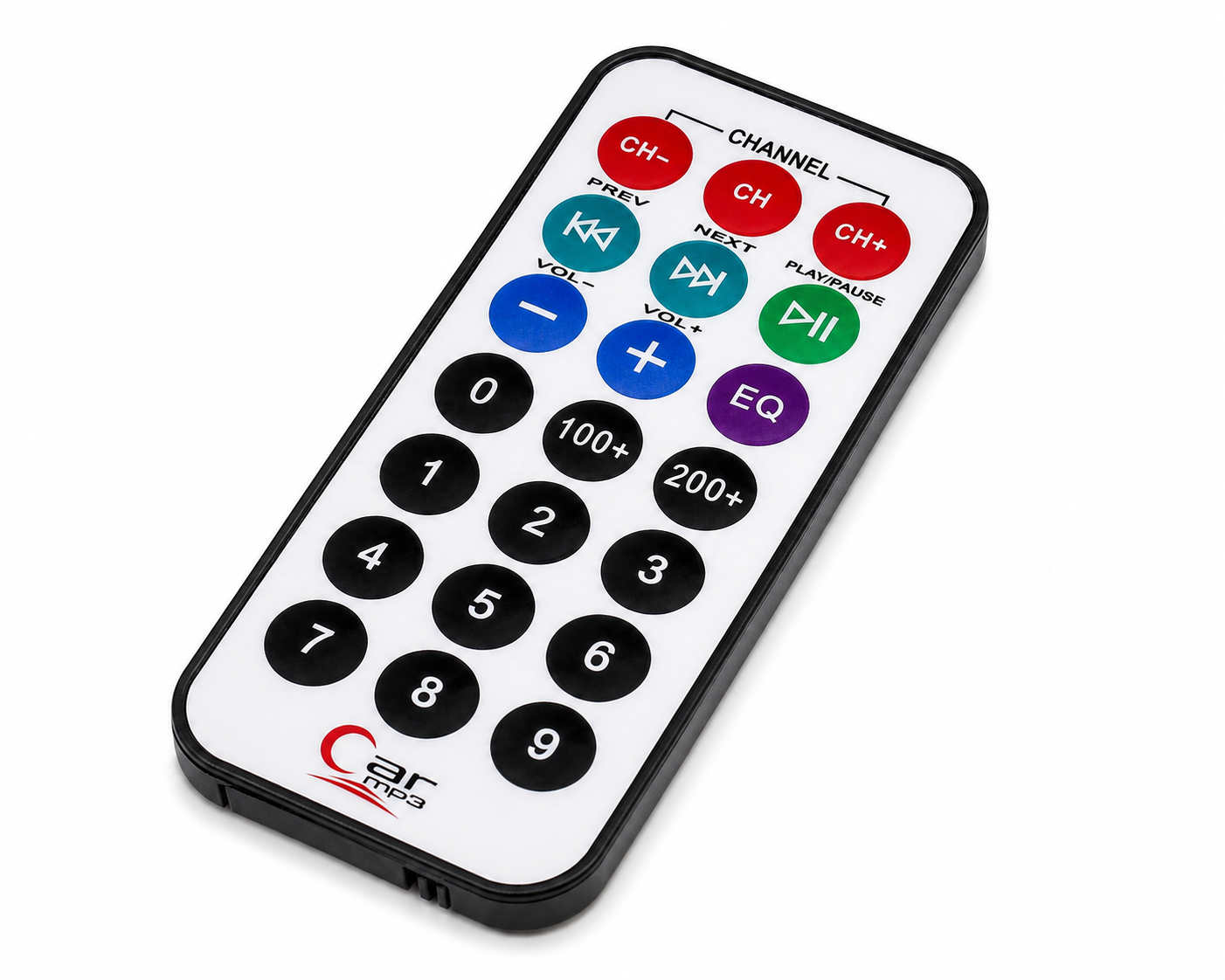
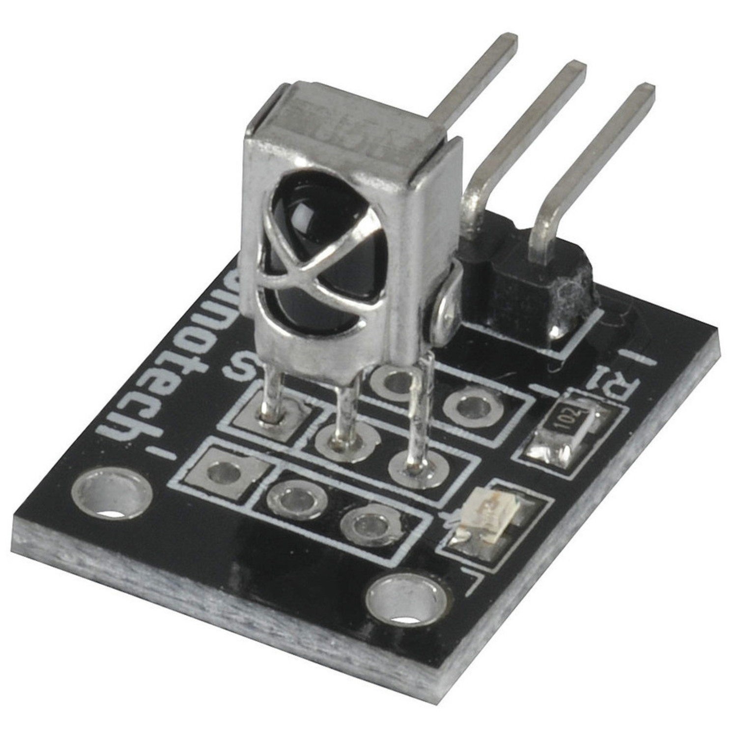
Shop/IOT/Water Flow Sensor - YF-S201B
SaleWater Flow Sensor - YF-S201B
IOT11 in stock

Water Flow Sensor - YF-S201B

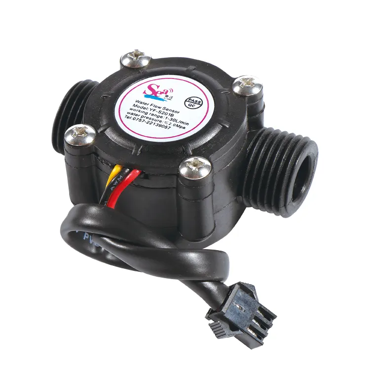
The YF-S201B Water Flow Sensor is a compact and widely used sensor for measuring the flow rate of water in pipelines. It is commonly used in water dispensers, irrigation systems, and other applications that require real-time flow measurement.

GHS 75GHS 60

Description

Key Features

  • Measures water flow accurately using a Hall-effect sensor.
  • Simple 3-wire connection (VCC, GND, Signal).
  • Compatible with most microcontrollers like Arduino, Raspberry Pi, and ESP boards.
  • Durable plastic body with high corrosion resistance.

Specifications

  • Model: YF-S201B
  • Operating Voltage: 5V–18V DC
  • Output Signal: Pulse signal (Hall effect sensor)
  • Flow Rate Range: 1–30 liters per minute (L/min)
  • Pulse Frequency: 4.5 pulses per liter (approx., varies by water pressure and pipe conditions)
  • Accuracy: ±10%
  • Maximum Pressure: ≤ 1.75 MPa
  • Pipe Diameter: G1/2 (1/2 inch)
  • Working Temperature: -20°C to 80°C
  • Material: Food-grade plastic

Working Principle

  • The sensor has a rotor with blades inside the water passage.
  • As water flows, the rotor spins, and a Hall-effect sensor detects the magnetic pulses generated by the spinning rotor.
  • The output is a pulse signal, where the frequency corresponds to the flow rate.

Pinout

  1. Red Wire: Power (VCC)
  2. Black Wire: Ground (GND)
  3. Yellow Wire: Pulse Signal (Connect to a GPIO pin)

Formula to Calculate Flow Rate

The pulse frequency output by the sensor can be used to calculate the flow rate using the formula:

Q=PulseFrequencyK×TQ = frac{PulseFrequency}{K times T}

Where:

  • Q: Flow rate in liters per minute (L/min)
  • PulseFrequency: Measured pulses per second
  • K: Calibration factor (usually 4.5 pulses per liter, check the datasheet)
  • T: Time interval (seconds) over which pulses are measured

Interfacing with Arduino

Hardware Setup

  1. Connect the red wire to the Arduino's 5V pin.
  2. Connect the black wire to GND.
  3. Connect the yellow wire to a digital pin, e.g., D2.

Applications

  • Water dispensers
  • Home automation (water usage monitoring)
  • Agricultural irrigation systems
  • Industrial fluid measurement
  • Cooling systems